Guidelines for Reducing Harmonic Distortion with Decoupling Capacitors
Any high-speed operational amplifier (op-amp) requires proper decoupling to attain maximum linearity performance. You can achieve this and minimize harmonic distortion with ideal decoupling capacitor placement in your op-amp circuit. Read on to learn more.
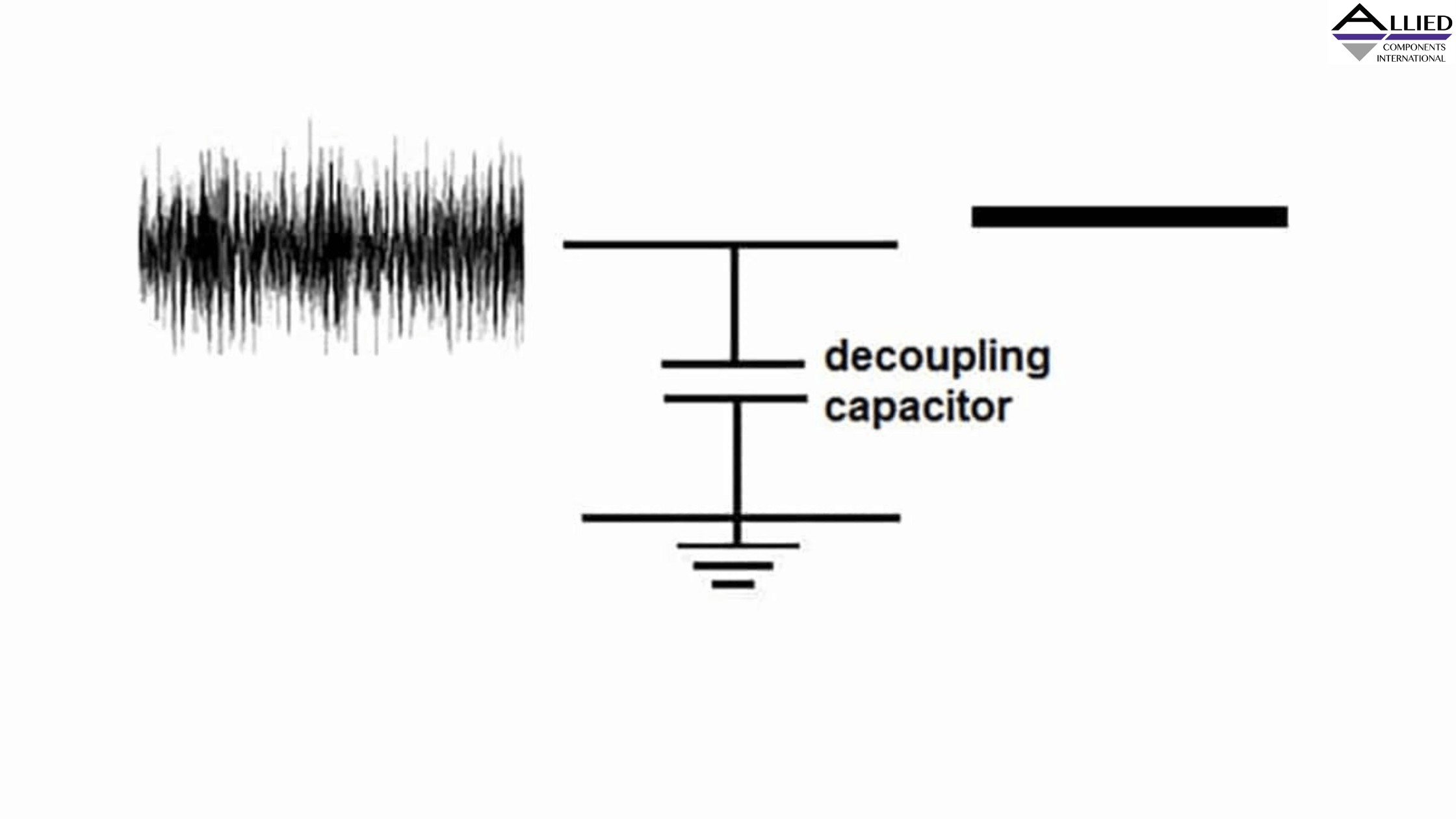
What are Decoupling Capacitors?
Decoupling capacitors are typically found on printed circuit board (PCB) layouts with semiconductor integrated circuits (ICs). They are also known as bypass capacitors and function as a type of energy reservoir. You can include the component in your op-amp circuitry to stabilize the voltage.
Poor Decoupling Capacitor Placement Can Increase Distortion
A certain level of power and ground conductors' inductance is common in PCB circuits. If you tried to supply high-frequency currents of a device through these components, this inductance would trigger some issues. One way to fix the problem is by placing decoupling capacitors close to the op-amp input pins. By functioning as a charge reservoir, your bypass capacitors would provide the required high-frequency currents and appreciably minimize the supply voltage variations.
Place the Bypass Terminal Away From the System's Inputs
Proper arrangement of components on a high-speed PCB circuit can help optimize the distortion performance. Consider the case of a non-inverting amplification phase using an op-amp in a small outline IC (SOIC). For better distortion performance with this configuration, you'll need to place the ground side of the bypass capacitor at a distance from the op-amp input and close to the load.
Also Read - How to Choose the Perfect Aluminum Electrolytic Capacitor
Why the Return Current Path Merits Consideration
When a negative-polarity signal is applied to the load on your high-speed op-amp, you can expect a return current to flow through the ground plane. Without proper placement of the bypass capacitor, this current can interfere with the voltage at the op-amp inputs. Consequently, it may cause a second harmonic distortion at the output voltage.
However, the return current flowing under the signal trace is comparatively smaller when the bypass capacitor's ground terminal is placed far from the inputs. In turn, there's less noise around the amp inputs or reduced harmonic distortions.
When the Load is Far From the System Output
Another possible op-amp PCB configuration has the load placed farther from its output. To minimize distortion in this scenario, you should still place the decoupling capacitor's ground terminal at a distance from the circuitry's inputs. Ensure to place the decoupling capacitor itself near the op-amp's power supply pins and its ground side near the system's output. This op-amp PCB layout will have a significant part of the return current flowing through the circuit's low-resistance path.
You can achieve maximum linearity from your high-speed op-amp with proper decoupling capacitor placement in the PCB layout. If you're looking to buy high-quality electronic components, visit our Allied Components International website. We manufacturer a broad range of devices engineered to meet your specifications, including capacitors, transformers, and inductors.
