Active Rectifier Circuits: What You Need to Know
The purpose of an active rectifier circuit is to straighten out alternating current while converting it to direct current. The rectifier gets its name from a Latin word that means "straight." Here are key points to know about an active rectifier circuit that delivers current in a single direction.
Inside an Active Rectification Circuit
At the foundation of the rectification, the circuit is a diode, which can also be referred to as a rectifier. Diodes are commonly used for the same purpose as rectifiers, except for certain applications. Once the voltage has reached a certain threshold, a diode by itself is unable to duplicate the positive side of the input signal.
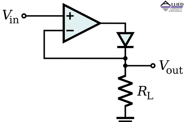
The other essential component of an active rectifier circuit is an operational amplifier. One of the advantages of an active rectifier is that it contains an extra diode to avoid output saturation. Power dissipates to the voltage level across the diode. When expressing the conversion process in an equation, this voltage level is multiplied by the amount of current flowing through the diode. A resistor is used in a circuit diagram to account for load resistance that allows for current to be converted to a voltage and compared with the input signal.
An active rectifier directs rectification patterns of a diode. The circuit uses negative feedback and amplification to avoid voltages that aren't compatible with the diode's ability to conduct current. The op-amp, which has a high open-loop gain, balances the load voltage with input voltage after power is fed back to the inverting input terminal.
The output triggers the diode to conduct current as the circuit follows the path of the voltage. When negative feedback appears, it indicates the inverting terminal's voltage is the same as the voltage of the non-inverting terminal.
Also Read - 14 Essential Electronic Components and their FunctionsHow to Prevent Oversaturation
A higher-quality active rectifier circuit is needed beyond simple applications that rely on output saturation. The negative differential voltage between terminals is multiplied by the op-amp's loop gain, leading to undesirable conditions, such as voltage volatility. This situation limits the circuit's function of rectifying high-frequency signals.
Also Read - 5 Common Applications of Flyback TransformersOversaturation can be prevented by connecting the input signal to the op-amp's inverting input terminal, while the output node is disconnected from the op-amp's output terminal. Ultimately, improvements will result from adding a diode to help prevent output saturation.
